Torque and Thermal Characterization of the AK80-9 BLDC Motor (T-Motor)
Dynamic Test
Setup for the Dynamic Test
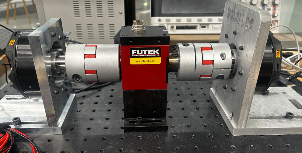
Two ACT-PACK motors are connected on opposite ends of a Futek torque sensor using a shaft and flexible couplers, with the entire assembly securely mounted on a test bed. The Futek sensor communicates with a Raspberry Pi via I2C for data logging, while the motors are connected through c-type cables and controlled using the Open Source Leg (OSL) libraries.
Methodology
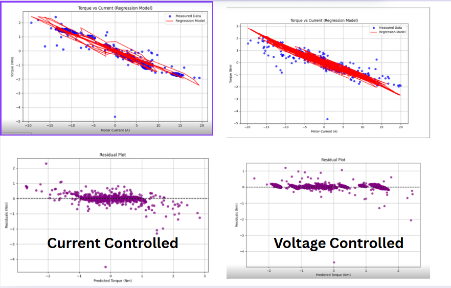
The motor on the left was operated in current control mode and the motor on the right in voltage control mode, with commanded currents from −10 A to +10 A and voltages up to 10 V. Data was collected using the Open Source Leg (OSL) logging function, recording timestamp, torque (Futek sensor calibrated readings), motor current, motor voltage, motor position, motor velocity, battery current, and battery voltage, and saved to CSV.
After collection, the following regression model was fit:
τa = τm − τf(θ̇a, Iq) − Baθ̇a − Jaθ̈a
Where:
- τa is the actual joint torque
- τm is motor torque
- Ba is viscous damping
- Ja is rotor inertia
- Friction τf(θ̇a, Iq) = sgn(θ̇a)(fc + fg|Iq|)
Results
- Torque constant: −0.145 Nm/A
- Coulomb friction (fc): 0.00787 Nm
- Gear friction (fg): 0.0211 Nm/A
- Damping coefficient (Ba): −9.1 × 10⁻⁵ Nm·s/rad
- Moment of inertia (Ja): 8.1 × 10⁻⁵ Nm·s²/rad
- Model captured 99.1% of the variance
- RMS residual: 0.067 Nm (1.43% of peak torque)
Static Test
Setup for the Static Test
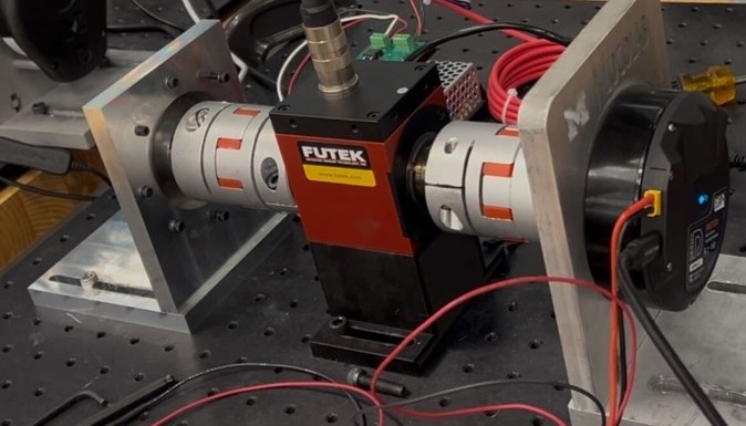
One ACT-PACK motor is connected to a Futek torque sensor using a shaft and flexible couplers, while the opposite end of the sensor is rigidly mounted to a fixed plate. The entire assembly is securely mounted on a test bed. The Futek sensor communicates with a Raspberry Pi via I2C for data logging, and the motor is connected through a c-type cable and controlled using the Open Source Leg (OSL) libraries.
Methodology
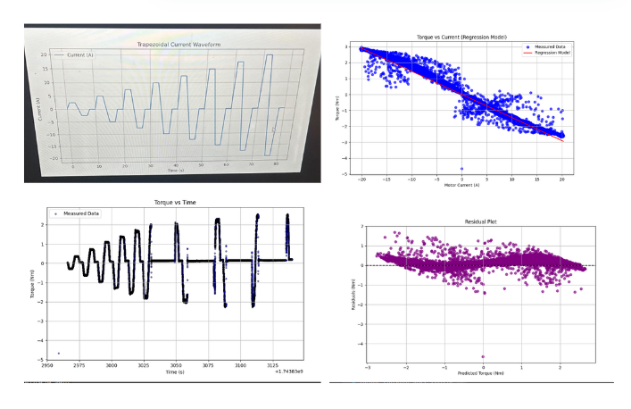
For the static tests, the motor operated in current control mode with a trapezoidal waveform: ramping to maximum in 1 second, holding for 2 seconds, ramping to negative maximum in 2 seconds, holding again for 2 seconds, then returning to zero and holding for 2 seconds. Peak current increased from 2.5 A to 20 A in 2.5 A steps. Data was logged similarly to the dynamic test and saved to CSV.
Friction terms fc and fg from Dynamic tests were used to adjust torque as:
τadjusted = τmeasured − (fg × Iq) + fc
The static model was identified by fitting:
τadjusted = Kt × Iq
The figure presents the current profile, torque profile, and the resulting regression model, yielding Kt = 0.145 Nm/A.
Drill Test
For the drill test, an oscilloscope, one ACT-PACK motor, and a handheld drill were used to actuate the motor.
Methodology
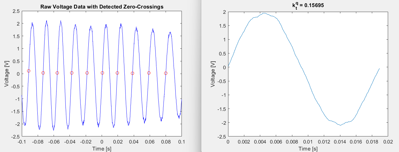
The drill test involves actuating the ACT-PACK motor at low speed using a handheld drill connected via a shaft. The motor leads are connected to an oscilloscope, which records the voltage over time. From the recorded waveform, the torque constant Kt is estimated using the equation:
Kt = (Vpk-pk / 2√2) / (3 × f × 2π × pole pairs)
Given the motor is delta-wound and has 21 pole pairs, this method provides an estimate of the motor’s torque constant based on the back-EMF profile.
Result
Results of the Drill Test shows the voltage vs. time plot and the estimated torque constant Kt.
The estimated torque constant Kt from the Drill Test was found to be 0.156 Nm/A.
The discrepancy in the torque constant observed between the static and dynamic tests versus the drill test arises because, during the drill test, the motor speed is too low for Coulomb and gear friction to significantly influence the measured torque constant.
Thermal Characterization of the new T-motors
Methodology
The thermal model used for thermal characterization is based on the Cauer thermal network, which represents heat transfer through a series of thermal resistances and capacitances arranged in a chain. This structure models the flow of heat through successive layers of a system.
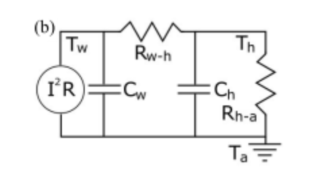
The parameters of the model indicated in the figure are as follows:
- Cw: Thermal capacitance of the winding
- Ch: Thermal capacitance of the housing
- Rw-h: Thermal resistance between the winding and the housing
- Rh-a: Thermal resistance between the housing and ambient environment
- T_w: Temperature of the winding
- T_c: Temperature of the case
- T_a: Temperature of the ambient
- I: q-axis Current
- R: Resistance of winding to q-axis current
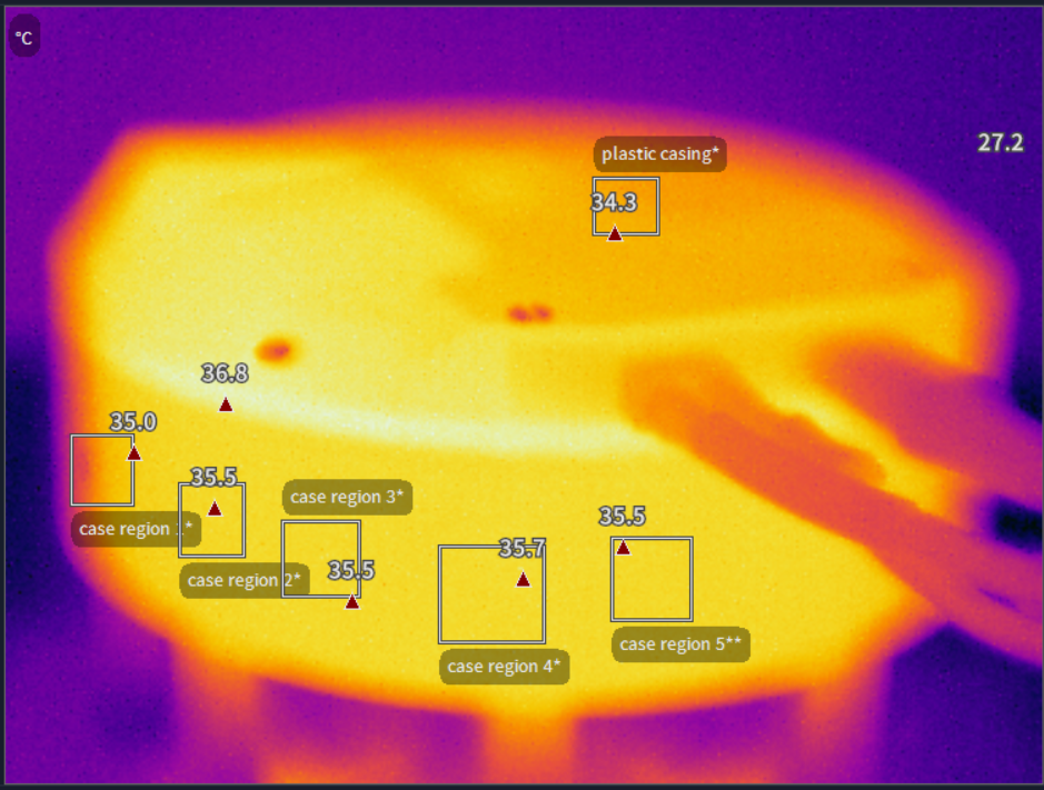
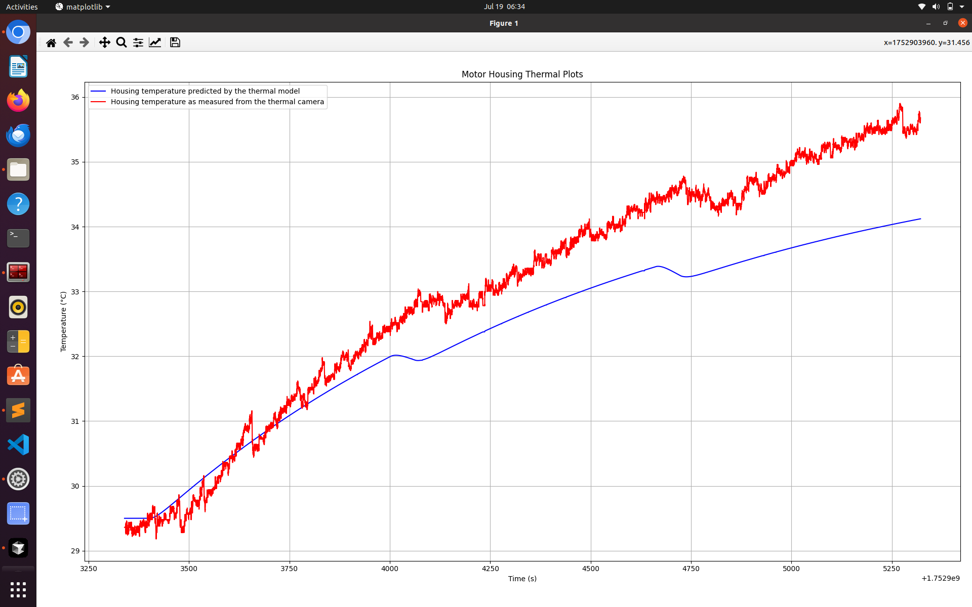
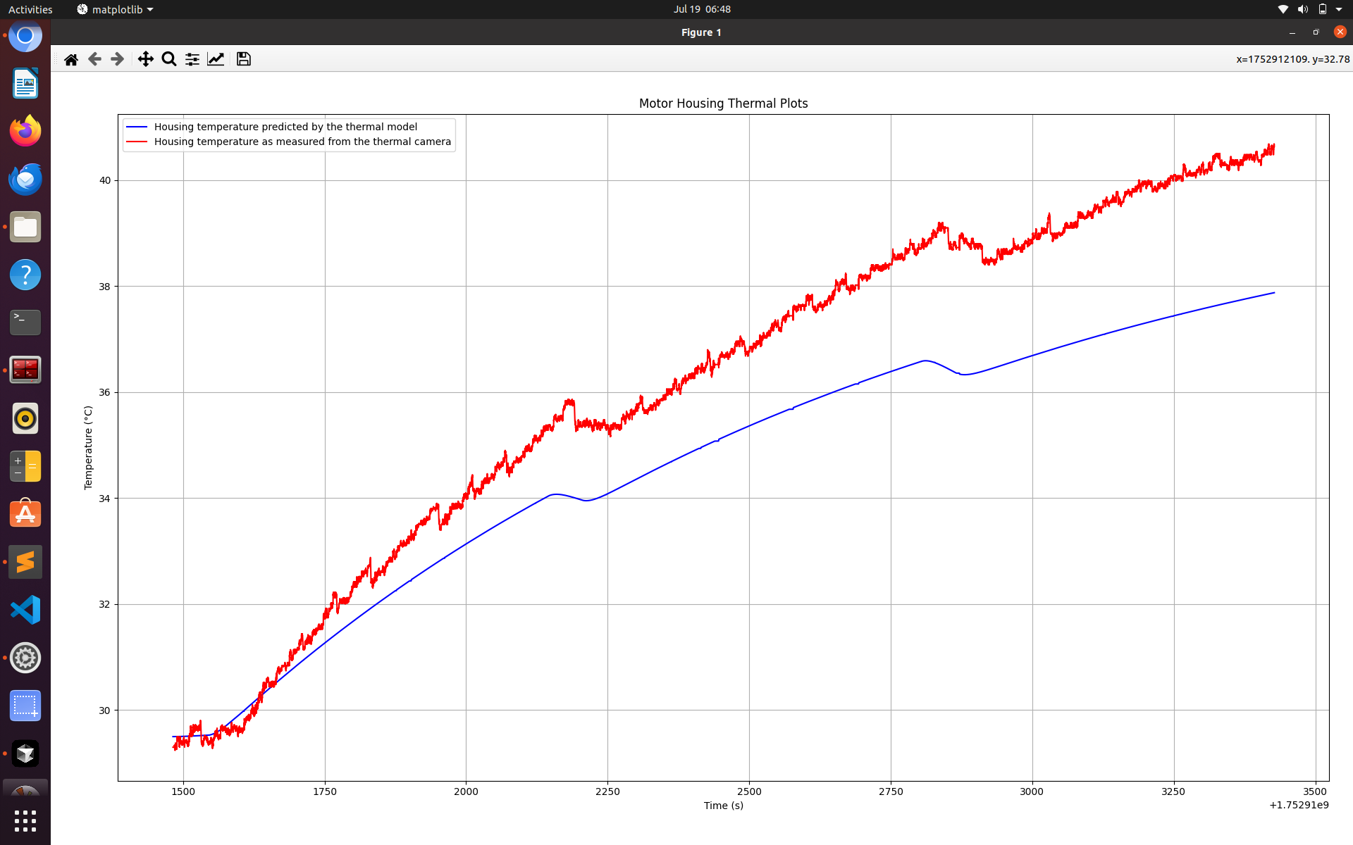
Since this thermal model had previously been used to characterize the earlier version of the Actpack, it was chosen again for the thermal characterization of the new Act-Packs. To analyze the variation in case temperature, q-axis currents of 6 A, 3.5 A, and 4.5 A were applied to the Dephy Drives across three separate tests. Test 1, which used 6 A, ran for 1 hour and 12 minutes, while the other two tests, using 3.5 A and 4.5 A respectively, each ran for 38 minutes. Thermal data was captured using an infrared camera (as shown in Figure 2), and the motor current was logged at 300 Hz using the OSL library.
This current profile was then the input to the thermal model, which uses Euler’s numerical method to solve a pair of first-order ordinary differential equations (ODEs) governing the system’s thermal behavior.
The time step for numerically solving the two ODEs was set to dt = 1/300 seconds,
corresponding to the inverse of the update frequency.
This allowed the model to generate predicted values of Tw and Th at each time step.
The predicted Th values were then used to plot their variation over time.
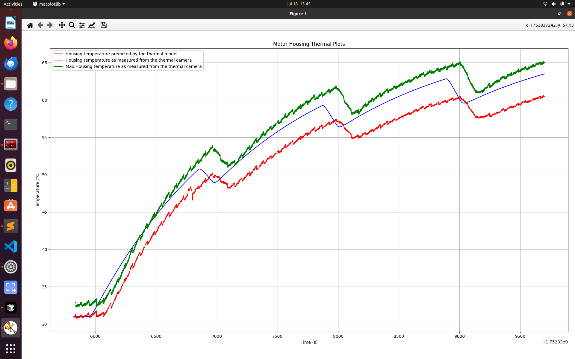
This predicted temperature profile was compared against the actual housing temperature data recorded by the thermal camera, effectively showing the rise in housing temperature over time alongside the model’s prediction. The thermal camera records the temperature at 30 Hz; interpolation was used to get the two data points on the same time scale, and the data was plotted in one graph.
Results and Discussion
The thermal model developed for the first version of the ActPack is applicable to the third version of the AK80-9 as well. Despite using the same architecture, the newer motors offer a higher torque constant while exhibiting thermal behavior that closely matches the original ActPack.
References
- U. H. Lee, C. -W. Pan and E. J. Rouse, "Empirical Characterization of a High-performance Exterior-rotor Type Brushless DC Motor and Drive," 2019 IEEE/RSJ International Conference on Intelligent Robots and Systems (IROS), Macau, China, 2019.